1. Board Components

- Mounting Holes (4 holes - 1 is shared with Raspberry-Pi Zero). This mounting hole location (upper left corner) is connected to GROUND.
- Wifi Module Header (8 pins), for ESP8266 ESP-01 module (optional)
- Communication Selection Jumper group.
- Firmware Programming Jumper (J7).
- Raspberry-Pi Zero Module mounting (4 holes), using standoff.
- Main Power Connector. Tip Positive, DC 12V 1A recommended.
- USB mini Connector, for Main Communication (using onboard CH340 USB to Serial Chip)
- Reset Button for STM32F407VET6
- Power Out Screw Connector (3 pins)
- Dual Row RJ-45 2X6 (12 Ports) for peripheral connections.
- System Control Signal Pull Up/Down Selection Jumper (J6)
- Header for SPI communication (8 pins).
- Header for I2C communication (5 pins).
- Header for Digital Inputs (10 pins).
- Raspberry-Pi Zero Module header (10 pins).
- Header for Firmware Programming (5 pins).
2. Peripheral Connections

Connection to all breakout boards are RJ45 (ethernet). CAT-5 or CAT-6 cables can be used in most cases, for longer cable run than 2 meters, CAT-7 is highly recommended. Connection of up to 10 meters has been tested with CAT-7 cable. The shield is connected to GROUND.
- X-Axis. Applicable Breakout Modules : AD1, AD2, AB1.
- Pin 1: STEP
- Pin 2: DIR
- Pin 3: Limit-P
- Pin 4: Limit-N
- Pin 5: Home
- Pin 6:Enable
- Pin 7: 5V
- Pin 8: GROUND
- Y-Axis.
- Z-Axis.
- A-Axis.
- B-Axis.
- C-Axis.
- [PWM-AUX.A]. Auxiliary PWM Outputs (1 to 4), group A. Applicable Breakout Modules: PW4, BB1.
- Pin 1: PWM1
- Pin 2: PWM2
- Pin 3: PWM3
- Pin 4: PWM4
- Pin 5: 5V
- Pin 6: 5V
- Pin 7: 5V
- Pin 8: GROUND
- [PWM-AUX.B]. Auxiliary PWM Outputs (5 to 8), group B.
- Pin 1: PWM5
- Pin 2: PWM6
- Pin 3: PWM7
- Pin 4: PWM8
- Pin 5: 5V
- Pin 6: 5V
- Pin 7: 5V
- Pin 8: GROUND
- [SPINDLE/LASER] Control. Applicable Breakout Module: BB1.
- Pin1: PWM
- Pin 2: DIR
- Pin 3: ENable
- Pin 4: Coolant Mist
- Pin 5: Coolant Flood
- Pin 6: Not Used
- Pin 7: 5V
- Pin 8: GROUND
- CNC [CONTROL]. Applicable Breakout Module: BB1.
- Pin1: Emergency Stop
- Pin 2: Feed Hold
- Pin 3: Cycle Start
- Pin 4: Safety Door
- Pin 5: CNC Reset
- Pin 6: Probe
- Pin 7: 5V
- Pin 8: GROUND
- [DIG.AUX]. Auxiliary Digital Outputs (1 to 8). CAT-7 cable is required (for GROUND). Applicable Breakout Module: BB1.
- Pin 1: AUX1
- Pin 2: AUX2
- Pin 3: AUX3
- Pin 4: AUX4
- Pin 5: AUX5
- Pin 6: AUX6
- Pin 7: AUX7
- Pin 8: AUX8
- [ALT.COMM] Alternate Communications: I2C and SPI. Applicable Breakout Module: BB1.
- Pin 1: SPI SCK
- Pin 2: SPI MISO
- Pin 3: SPI MOSI
- Pin 4: SPI CS
- Pin 5: I2C SCL
- Pin 6: I2C SDA
- Pin 7: 5V
- Pin 8: GROUND
Examples of Peripheral Connections:
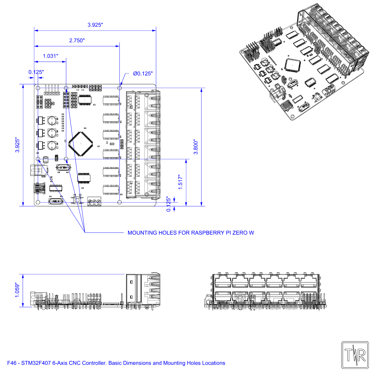
3. Mounting Holes
Mounting Holes Locations. The holes' size is 0.125" (3.16mm), the pad size is 0.225" (5.72mm). Suitable standoffs and screws are 4-40 or smaller for imperial, M3 or smaller for metrics. For mounting the Raspberry Pi Zero W, M2.5 standoffs are recommended due to the smaller mounting holes on the Pi Zero.
If the final integration requires a chassis ground, the upper left hole/pad is connected to ground.
4. Jumper Settings
(3) Communication Selection Jumper group

Default: Communication is via onboard USB to serial (CH340 chip).

Communication via Raspberry-Pi Zero

Remove all jumpers when the optional WiFi Module is connected. The user can also connect a TTL-Serial UART directly. Popular choices include CH340, FTDI, CP2102, or another micro-controller for custom implementations. Connect the UART TX pin to the indicated rx pin, similarly RX to tx, and Ground to gnd. Comm Baud Rate is 921,600.
(4) Firmware Programming Jumper (J7)

Default: jumpered for normal operation. Remove jumper for firmware programming.
(11) System Control Signal Pull Up/Down Selection Jumper (J6)

Default: Apply Pull-Up to Control inputs
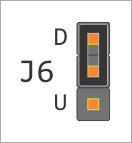
Apply Pull-Down to Control inputs.
5. Board Connections

Bottom silkscreen showing board connections and pin labels.